The Pier Mount Without The Tube
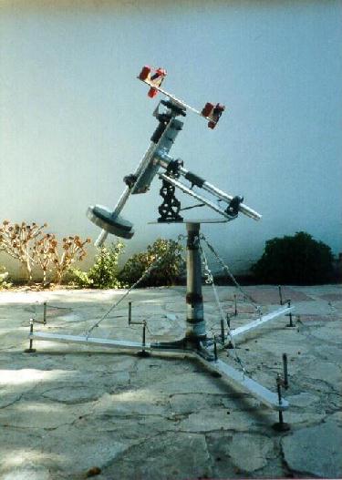
The following describces the construction of the mount (from top to bottom) --
- The Platform
- I began with the most expensive components -- the pillow blocks.
Their inner diameters were approximately 1-1/4 inches.
- After purchasing them, I purchased hollow, aluminum tubes for the
Declination and Right Ascension Shafts and a solid aluminum tube for
the Extension. Their outer diameters were all slightly larger
than 1-1/4 inches so that they could be shaved down to tightly fit
inside the pillow blocks.
- The Right Ascension Shaft was cut to approximately two feet long.
- The Declination Shaft was also cut to approximately two feet long.
The Extension for the Shaft is a one-foot long piece of
solid aluminum stock. The interior of the bottom end of
the Extension was threaded (male end), using a lathe, and is
inserted into the bottom of the Declination Shaft. The
bottom of the Declination Shaft was threaded (female end) and
receives the Extension. The purpose was to eliminate the
Declination Shaft from sticking out while transporting and
carrying it. Also, the Extension was constructed from
solid tubing in order to increase weight for counter balancing
purposes.
- The Shafts were then shaved down to the inside diameter of the
pillow blocks. The Extension was also shaved down to the
same diameter in order to match its size to the Declination
Shaft's size. Due to the precision required, a lathe was
used to do these.
- The Clamp and the Collar were also machined on a lathe.
The interior diameter of the Clamp was machined to match the
outer diameter of the Extension. It was drilled
width-wise. Then, a cross cut was made through it at the
location of the middle of the drill. A hex head bolt was
inserted into the drilled hole and that is how the Clamp is
fastened to the Extension.
- The Collar was machined to match the outer diameter of the
Extension and the inner diameters of the Counterweights.
Its length was cut so that two Counterweights could be placed on
it. In this case, the two Counterweights weigh 25 pounds
and 10 pounds, the weight of the telescope's mirror and mirror
cell.
- For the Hitch Pin, a hole was drilled near the bottom of the
Extension for it.
- Next, I purchased the aluminum plates for the pillow blocks and the
telescope tube. They were cut to the desired lengths and the
edges were rounded off to decrease the chances of people cutting
themselves on them.
- The horizontal base plate was left over from a friend's previous
equatorial mount project. Fortunately, it was the correct
length and width for my purpose.
- Flanges were handmade on a lathe. The connect the Right
Ascension Shaft to the Declination plate and the Declination Shaft to
the telescope tube plate. They are attached to the plate via 4
bolts each and to the Shafts via hex head bolts threaded into the
plates, also 4 each. The increased sturdiness of this part of
the mount was well worth the effort put into making these flanges.
- The interior of the Declination setting circle was drilled larger so
that it could be slipped over the Declination Shaft's flange.
It was held in place by a a collar that was handmade on a lathe.
Threaded through the collar are nylon bolts that hold the
setting circle in place. Their tightness are adjusted so that
it can be adjusted by turning it by hand.
- Part of a piano hinge was used to connect the horizontal base plate.
A riveting tool was used to attach the horizontal base plate
and the Right Ascension plate.
- A car jack is used to obtain the correct angle for the varying
latitudes at which I observe. It was purchased from an
automobile junk yard. It was bolted to the horizontal base
plate and slides up and down on the bottom of the Right Ascension
plate.
- Blocks of wood were cut to match the width of the telescope tube
plate. The wood was then shaved to fit the contour of the
tube. Pieces of felt were glued to the blocks in order to
eliminate damaging the tube. The tube is held in place via two
ratcheting tie downs (typically used for something else such as
holding luggage onto car roofs) that are bolted down between the
plate and the blocks of wood.
- The two 4-inch long, hollow pipes attached to the shafts located
between the four pillow blocks are used to "clamps" down
the shafts in place. Nipples were welded onto the pipes.
Into these nipples, winged bolts thread into them. The
winged bolts are threaded through the Right Ascension plate and the
Declination plate. The clamps can be adjusted to the desired
tension. Inside, they are lined with rubber. This
protects the shafts from being damaged.
- The Stem
- The Stem was also part of the wheel grinding pedestal. It was
initially around three feet long. The system was tested to
determine how much it could be shortened. (This would reduce
the overall height of the system.) Approximately 15 inches
were then cut off of it.
- A male-to-male coupling was welded on to the top of the Stem.
Through the male-to-male coupling, three eye bolts were inserted.
These were used to attach the Turnbuckle-Cables to it.
- The Base
- The Base was part of a wheel grinding pedestal. Nine holes
were drilled in it where it could be attached to the legs.
- Onto the top of the Base, a female-to-female coupling was welded.
- The Cables
- The Cables were cut to lengths of 30 inches each.
- Loops were made at their ends and they were clamped down.
- The Legs
- Like most parts of the mount, they were fabricated from pieces of
aluminum.
- The ends are rounded off so that people, including me, don't hurt
themselves if striking them.
- Six holes were drilled in each of them. Two were for the
levelers, one was for the eye bolt (that the cables attached to), and
three were for the Base.
- Initially, the inner three levelers weren't created. However,
after testing the system, the interior of the mount sagged under the
weight of the mount and the telescope, so they were added on later.
The mount stands approximately five feet tall. It needs to be this high
so that the bottom of the telescope tube doesn't strike the Cables. Also,
the tube can be positioned to view any location in the sky. (Some designs
prevent the ability to view a triangular part of the sky near Polaris.
Since it can be avoided, I don't want the limitation.)
Return to the previous page . . .
Created: November 4, 2001
Updated: August 13, 2003